XL (Black Chassis) Guides

You have touched down in our User Guide area for LiteHawk XL (Black Chassis) helicopter


 LiteHawk XL (Black Chassis) Instruction Manual


LiteHawk XL (Black Chassis) How to charge

Before charging the battery, please ensure that you have read ALL of the information in this manual, download is above. Failure to do so will increase the risk of a potential problem.
  • 1. Plug the supplied wall charger in to any 120V outlet. *Green light indicates there is power going to the charger*
  • 2. Unplug the red battery connector from the helicopter if plugged in. 
  • 3. Plug the red connector from the battery into the charger. *The LED will change from GREEN to RED indicating that the battery is charging*
  • 4. Once the LED changes from RED to GREEN, un-plug the battery from the charger. *Charge time is approximately 1 hour* Do NOT let battery charge for more than 2 hours.
  • 5. Unplug the battery from the charger and plug in the red connector into the side of the helicopter.

It is normal for the battery to get warm during the charging process. Do not charge the battery on a surface that is flammable or can be damaged by heat. 

  • Do not leave the battery and charger unattended while charging.
  • Do not store the battery plugged into the charger

Remember

  • Recharge the battery for at least 20 minutes if storing for more than 24 hours. Failure to do so will damage the battery pack.
 LiteHawk XL (Black Chassis) - How to sync - Controller Guide
  • Place the helicopter on a flat surface.
  • Turn your remote controller On, you will see a flashing red LED light indicating the power is on.
  • Plug the battery into the helicopter, move the switch to the on position and place the helicopter on a flat surface approx. 6 feet away.
  • You will see lights on the helicopter come on.
  • Push the throttle lever to the top and back down to sync the helicopter.
  • Slowly push the throttle lever up and your LiteHawk will begin to hover. This may take a little practice. If your LiteHawk does not stay straight, adjust the trim wheel by turning it in the opposite direction that the LiteHawk is rotating.
 
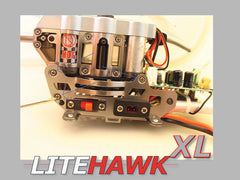
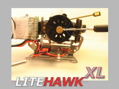
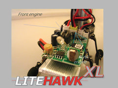
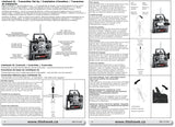
LiteHawk XL ESC Board Removal and Installation
REMOVAL PROCEDURE
1. Remove Canopy by removing the four screws (two per side) and release from screw bosses.
2. Carefully snip cable tie that retains battery under the board and put the battery aside. Caution: Do NOT damage the LiPo battery pouch in any way. Damaged batteries can pose a fire risk.
3. Carefully snip cable tie that retains the Antenna Wire to the Landing Gear and unwind the wire.
4. Remove plug-side Lower Chassis by removing Landing Gear screws and Chassis screws as shown below in picture 1. Caution: Handle antenna wire gently or it me break away from the ESC board. If this happens, simply solder it back in place.
5. Remove three plugs from the board. These plugs are shown along rear edge below in picture 2.
6. Remove the three screws that secure board, as shown below in picture 3.
7. Snip off Cable Tie to release the assembly. See picture 4
8. Lay down the separated board and harnesses (on Chassis plate) down as shown in picture 5.
9. Using your soldering iron, reflow the four existing lead points on the ESC board and gently pull away the leads from the board. Caution: Do not overheat the board as board delamination can occur. Be accurate so as to not unsolder adjacent connections.
10. Lift away the ESC board.
INSTALLATION PROCEDURE
1. Using your soldering iron and referring to the XL ESC Board Wiring Reference, reconnect the switch and battery harnesses onto board.
2. Replace the board onto the frame and secure with the three screws.
3. Replace Chassis Plate and Landing Gear and attach the five screws.
4. Replace Battery and secure using a Cable Tie.
5. Referring to the XL ESC Board Wiring Reference, Reconnect the plugs as indicated.
6. Use a cable tie to secure plug harness cables to the underside chassis plate, away from Main Gears.
7. Install the Canopy and put in the screws.

Changing XL Main Gears (XL Silver Chassis shown, no worries the technique is the same)
  • To change your main gear on the XL, start by removing the canopy, then remove the two screws indicated (with the blue arrows) in the first photo, do the same on the reverse side of the heli. Note there are two screws that are longer than the others, those go in the landing gear at the back.
  • Next remove the outer chassis by removing these three screws (indicated in blue picture 2) then do the same for the other side of your heli (be careful there are wires attached to the chassis that are soldered to the board so you want to be gentle, so as not to accidentally seperate them from the board).
  • You now have access to your main gear, turn your heli so you see the underside, find the brass block, and loosen the screw (indicated with the blue arrow picture 3).
  • Now just slide em off and slide in your new ones when you tighten the screw in brass block, on your new gears the screw should be aligned with the small flat spot on the main rotor shaft (or you will get slippage, and therefore not enough lift).

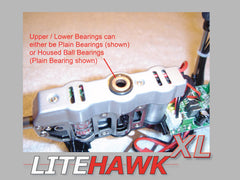
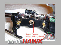
XL Upper and Lower Rotor Assembly Removal and Installation (XL Silver Chassis shown)
REMOVAL PROCEDURE
  • 1. Remove Canopy by removing the four screws (two per side) and release from screw bosses.
  • 2. Remove each Lower Chassis (one per side) by removing Landing Gear screws (two per side) and Chassis screws (three per side) as shown below in picture 1. Caution: Handle antenna wire gently or it me break away from the ESC board. If this happens, simply solder it back in place.
  • 3. Loosen Lower Main Gear setting screw and slide the gear off the Upper Rotor Assembly shaft. Gently pry off the Upper Main Gear from the Lower Rotor Assembly shaft. Now the Upper and Lower Rotor Assemblies can slide out from the top as shown below in Picture 2.
  • 4. Remove Rotor Blades if required.
INSTALLATION PROCEDURE
  • 1. Inspect the top and bottom of the Motor Mount to ensure the corresponding bearings are still correctly seated as shown below in pictures 3 and 4.
  • 2. Insert the Lower Rotor Assembly taking care not to dislodge the Lower Bearing, as shown above in picture 4. Lubrication is optional but recommended if your model contains Plain Bearings as shown in Pictures 3 and 4.
  • 3. Install upper Main Gear by aligning the flat on the Lower Rotor Assembly shaft with the corresponding flat on the Upper Main Gear.
  • 4. Install the lower Main Gear by aligning the flat on the Upper Rotor Assembly shaft with the setting screw on the lower Main Gear. The brass collar should point down. Compress the stacked up shafts to take up any lash. Tighten the screw.
  • 5. Install the Lower Chassis plates and Landing Gear and put in the screws.
  • 6. Install the Canopy and put in the screws.

LiteHawk XL How to change the main motors (XL Silver Chassis shown)
  • Start by removing your canopy,then remove the two screws indicated (with the blue arrows) in the first photo, do the same on the reverse side of the heli,note there are two screws that are longer than the others, those go in the landing gear at the back.
  • Next remove the outer chassis by removing these three screws (indicated in blue in second photo) then do the same for the other side of your heli (be careful there are wires attched to the chassis that are soldered to the board so you want to be gentle, so as not to accidentally seperate them from the board)
  • Now you have access to your main gear, turn your heli so you see the underside, find the brass block, and loosen the screw (indicated with the blue arrow in picture 3). Now just slide em off.
  • Flip the heli over now so you can see the top of the motor housing cap, and remove the two screws (indicated in blue picture 4) so that you can remove the cap.
  • Now look at the front of your heli, so you can see the main board, and unplug the two plugs for the main motors (picture 5). IMPORTANT! The screws you are removing from you engines are shorter than the others, it is important that you use the same screws to remount the new motors ... accidentally using a longer screw to mount your new engines , may permanently damage them!
  • Back to the underside of your heli, you can now remove the engines by removing these screws (picture 6).
  • When re-installing your engines, there are a few important things to remember, the engine with the longer shaft ... is the rear motor (it is also the one with the yellow plug), and when looking at the face of the engines you will notice three holes in each engine, two of those holes are for the screws that secure each engine, make sure that the other one is facing toward the tail (on both motors).
  • Now just reverse the steps you followed to get here, to put your heli back together!