GOBI FAQ


LiteHawk GOBI Features:

  • Polycarbonate body shell includes driver and navigator figures and is available in Red or Yellow.
  • Did you know it's the very same material used in bullet-proof vests? It's strong and flexible, so this outer skin helps protect your new R/C vehicle.
  • We also paint the body "from the inside" so it is very resistant to scuffs and scratches!
  • High Travel Friction Shocks are standard equipment on GOBI
  • Soft All-Terrain Rubber Tires for superior grip and performance
  • 2.4Ghz Digital Pistol Grip Controller with soft steering wheel gives you fully proportional control.
  • Includes Wall Mount Charger and NIMH Battery
LiteHawk R/C Car and Truck Terms 101
Transmitter: The hand-held radio unit that sends throttle and steering inputs to your model. Also known as the radio or controller.
Servo: Small motor unit in your model that operates the steering mechanism.
ESC: The Electronic Speed Control provides digital proportional throttle control to the model’s motor based upon your throttle input on the radio.

LiteHawk GOBI - NIMH Battery and Charger Instructions:

Your New LiteHawk comes with a rechargeable NIMH 7.2 Volt battery. This battery powers the vehicle.
Please read the following information before using your new LiteHawk.

STEP 1: Remove the wall plug charger from the package and plug it into the wall. When plugged in a green LED light will come on.


STEP 2: Connect the 7.2 Volt battery to the charger. The green LED light will turn to red.


STEP 3: When the LED indicator light on the charger turns back to green, the battery is fully charged.


Charge times are (3.5-4.5hrs) do not leave on charge overnight. Battery should be unplugged from the charger after a maximum 8 hours.
STEP 4: Unplug the battery from the charger and remove the charger from the wall plug.
STEP 5: Install battery into your vehicle.

During charging:
- It is normal for the battery to get warm during the charging process. Do not charge the battery on a surface that is flammable or can be damaged by heat.
- Do not leave the battery and charger unattended while charging.
- Do not store the battery plugged into the charger


 LiteHawk GOBI - Body Removal

To remove (flip forward) body, first find and remove all body clips. There are two on the hood,

and two near the rear, on both sides.

Now, from the rear, lift up and over the front body posts. The body will flip all the way forward.

TIP- You can easily remove the body from the chassis to facilitate repairs, by removing these two Hinge pin screws. 

To replace, reverse the procedure.

LiteHawk GOBI - Battery Installation
Place your GOBI on a clean flat surface. Avoid areas where small parts may be lost. The battery is housed in the battery compartment located in the bottom of the chassis. You will see the lock bar or post that runs across the chassis with a body clip holding it in place.


- Remove the body clip and remove the lock bar, open the battery compartment door.

-Pass the battery connector through the hole located in the bottom of the battery compartment, out towards the ESC.


- Place your fully charged battery in the battery slot.

- Close the battery compartment door and slide the lock bar back into place. Secure by re-installing the clip. 

Connect the Battery to the ESC.  Don’t force it, it only goes one way!

Remount your GOBI Body and you are ready for the road.

 Starting your GOBI

-Plug in your Battery, then turn on the Power switch on the Radio, it will start blinking green and red.

-Then turn on the little red switch on the ESC. A red LED light will start blinking in the ESC. and if your wheels where turned to one side, they should snap to the center.

The vehicle is basically bound to the radio now.. just move any control and the lights will stop blinking in the ESC and remain solid. The Radio control will now be a solid Green.


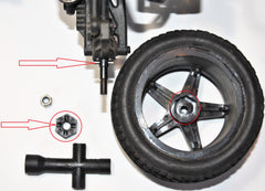
 LiteHawk GOBI  Wheel Removal 

  •  Use the T wrench included with the GOBI, to unscrew the nuts.

  • It is a 7mm socket. Pull off the wheel. The Rear wheels are the drive wheels and they have a Hex nut that attaches the rear axles to the wheels with an axle pin. Take special care when removing these rear wheels not to lose these pins, as they can fall out very easily.

  • You can see how the Axle pin fits into a slot in the Hex nut, and the Hex nut fits into the Wheel Rim, which is all locked into position with the Ny-Loc Wheel nut. 
  • The front wheels are not drive wheels and do not have Hex nuts or Axle pins to worry about. Just remove the Wheel nut and pull off the tire.

 LiteHawk Gobi - Shock Removal. Front and Rear.
Problem with your LiteHawk Gobi Shocks.. need to repair or replace them.. change the ride height? Look here!

  • Fold your Gobi body out of the way or you can remove the body entirely to make the job a little easier. Described above.
  •  You have to remove the front body mount to be able to access the top shock screws. Just remove these two screws and lift out. Now you have access to the front shocks. 

  • Remove the top and bottom screw from the shock and lift out.

  • Take note which position the bottom of the shock is screwed into so you can replace it correctly. It comes from the factory set at the inside position to give the Gobi a high ride height.. move it to the outside position for a lower ride height.

  • For the rear shocks.. it is the same thing. Remove the upper and lower screws to lift out the shock. 

  • Take note which hole the lower shock is screwed to. It comes from the Factory set at its highest setting.. closest to the body.

  • You can adjust your ride height, lowering it, by moving the shock to a hole further from the body.

 LiteHawk GOBI Front C-Hubs, Steering Knuckle, and Axle.

  • Remove the front wheel. Loosen the Axle Pin but don't remove it.

  • Now remove the screws to the steering linkage, the upper suspension, and the lower suspension. Remove the Axle assembly. 


  • Remove the Axle pin. Notice the slot cut away in the Axle that the Axle pin slides through, when the Axle is inserted into the Steering Knuckle.

  • The Axle pin also locates and holds the Axle and Steering Knuckle into the C-Hub, so that the wheel can turn side to side and still rotate on the Axle. Reassemble in reverse order.

 Upper and Lower Front Suspension Arms

  • Follow above instructions to remove the front wheel and the C-Hub with the Axle assembly intact from the Upper and Lower Suspension Arms. Now remove the Suspension Arm Hinge Pins from the Chassis side of the Upper and Lower Suspension Arms. 


  • Reinstall in reverse order.

 Shock Tower with Lower Body Mount Assembly, and The Steering Assembly.

  • Follow above instructions, to remove both of the Front Upper Suspension Arms. You can leave the arm attached to the Wheel assembly, and the Wheel assembly can be left attached to the Lower Suspension Arms.  Remove the Suspension Arm Hinge Pins from the Upper Suspension Arms, and lift to the side. You want to remove the entire Shock Tower/Lower Body Mount Assembly from the Chassis.

  • Now remove the four screws holding the Shock Tower and Lower Body Mount Assembly, and lift it out.


  • To gain access to the Steering Assembly, remove the six screws holding down the Upper Chassis Plate. Remove the two screws holding the two Steering Link Arms to the Steering Assembly. Remove the Link attaching the Servo Horn to the Steering Assembly. Lift the Upper Chassis Plate and set aside.

  • Carefully lift out the Steering Assembly. Take note of the Steering Pins, and their location for reassembly.

  • Reassembly in reverse order.

 Servo Access.

  • Follow above instructions to remove the Upper Chassis Plate, and set aside. You can leave the Steering Link arms attached to the Steering Assembly. Just remove the Servo Horn Link from the Steering Assembly.

  • Now remove the five wire Servo wire Harness from the ESC. and the two screws holding the Servo to the Chassis, and remove.

  • Reassemble in reverse order.

 Rear Axle Assembly, Rear Lower Suspension Arm.

  • Remove the rear Wheel, and carefully remove the Hex nut and the Axle pin. Then take out the screw holding the Upper Suspension Link to the Rear Upright, and remove the Rear Upright Hinge pin, the Axle will slide out.


  • To remove the Lower Suspension Arm, disconnect the lower shock support from the arm, and take out the Rear Suspension Hinge Pin at the Chassis.


  • Reassemble in reverse order

 Rear Gear Box- Differential, Spur Gears, Motor, Pinion Gear.

  • The Gear Box is some thing that you should be removing once in a while, just for maintenance purposes. It is sealed inside with a bead of grease, that traps dirt and dust from getting in. That grease needs to be cleaned out and replaced occasionally. That is always a good time to have a look at the gears.
  • First disconnect the power wires to the motor, and cut off the plastic tie strap. ( you can find these straps at Automotive supply stores.. or sometimes the Dollar Store ). Disconnect the top of both shocks from the shock tower.

  • Now remove the six screws from the Upper Chassis that hold the Rear Shock Tower, Rear Body Mount Assembly, and the Rear Bumper on. Also remove the two screws on the bottom of the Chassis that also hold the Rear Bumper on.


  • Lift the whole frame work off. 

  • Remove the screws holding the two Upper Suspension Links to the Gear Box.

  • You can now lift the Gear Box out.
  • Remove these four screws to open the Gear Box.

  • With the box open, the Spur Gear and the Differential just lift out. Be careful of the Spur Gear Pin, as it just lifts out too. 
  • To remove the Motor, you first want to remove the Rear Motor Housing by taking off these two screws. Notice where the motor power wires run, for reinstallation.

  • Now loosen the set screw in the Pinion Gear with an Allen wrench, and remove it from the Motor shaft. Then remove the two screws closest to the Pinion Gear to remove the Motor from the Motor Mount. The other two screws hold the Motor Mount to the Gear Box.

  • Reassemble in reverse order. Don't forget to put a new bead of grease down, around the seams. 

     Rear Shock Tower

    • Follow the first part of the above procedure, Gear Box, up to where you lift off the Rear Shock Tower, Body Mount and Rear Bumper Assembly. 

    • Remove two screws from the front of the Shock Tower.

    • Now remove the four screws from the back of the Shock Tower.


    • Carefully separate out the Shock Tower and supports From the Body Mount Assembly.

    • Reassemble in reverse order. Make sure that the Shock Tower Support legs mounting holes are set to the inside.